Open Micro-Manipulator turns ordinary stepper motors into a sub-micrometer motion platform
A newly popular open hardware project combines 3D-printed mechanics, magnetic encoder gearing and closed-loop control. Its useful promise is real, but the build is still a precision experiment rather than a ready-made lab instrument.

The Open Micro-Manipulator is having a very good week on Hacker News for a reason that has little to do with fashionable software. It is an open hardware project that uses ordinary stepper motors, 3D-printed or machined parts, magnetic encoders and custom firmware to make a compact three-axis platform capable of extremely small commanded movements. The repository describes steps down to 50 nanometres and a sub-micrometre motion-control platform for optical alignment, microscopy and probing electronic components.
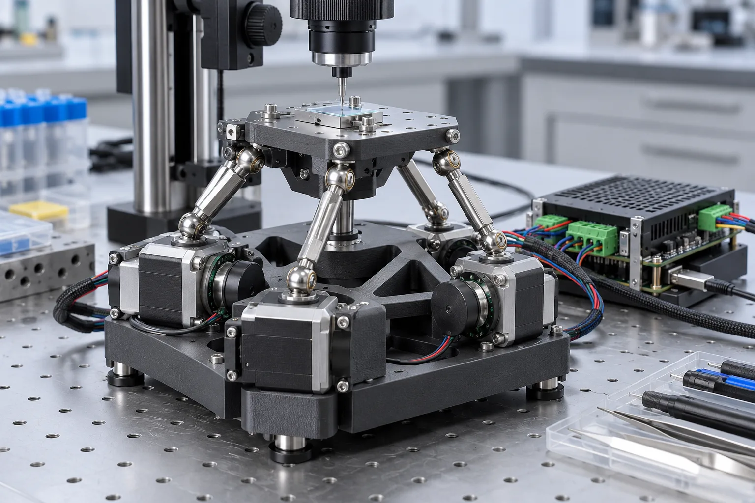
That description needs one important qualification. A 50 nm step is a resolution claim, not a promise that the complete machine places a tool 50 nm from its intended position under every condition. The project itself says that absolute accuracy is significantly worse. Temperature, print quality, linkage geometry, encoder alignment, friction, vibration and calibration all matter. The interesting story is therefore not that a cheap motor has somehow become a laboratory nanopositioner. It is that an open design makes the control architecture, mechanical compromises and failure modes visible enough for people to study and improve.
The project appeared near the top of the Hacker News front page on October 18, 2026, gathering more than 180 points in the snapshot available on October 19. A linked Reddit discussion was also created the same day. That attention makes it worth examining as a build rather than repeating the headline number.
What the project actually is
The MicroManipulatorStepper repository contains the mechanical design, electronics, firmware and software needed to assemble a motorized XYZ stage. Its stated target users include people working on optical alignment, electronic probing and microscopy. The device is not presented as a general-purpose desktop 3D printer. It is a small motion platform to which a probe, tool or microscope-related fixture can be attached.
The mechanism uses a parallel kinematic structure with miniature ball joints. Three motor-driven linkages move the working point in three dimensions. That arrangement is different from the familiar Cartesian stack in which one linear rail rides on another. A parallel mechanism can keep moving parts compact and can provide useful stiffness, but it also makes the relationship between motor angles and tool position more complicated. The firmware must continuously apply a kinematic model, and the physical build has to match the dimensions assumed by that model.
The repository lists 240 commits, a hardware version 4.0 design, a C++ firmware tree, electronics files, FreeCAD models, printable STL files and a Python interface. At the time of review it had roughly 2,100 stars and 276 forks. Those numbers show genuine interest, but they do not prove that thousands of complete machines exist. For an open hardware project, forks and stars are better read as evidence of people examining the design than as a deployment count.
The project is released under an MIT license that explicitly covers the software, hardware design, documentation and concept. The license permits copying, modification, distribution and sale, subject to preserving the notice, while providing the work without warranty. That is a practical license for experimentation and commercial derivatives, but it does not remove the responsibility to validate a machine before putting it near a valuable sample, a laser or a live circuit.
Where the small numbers come from
The most striking technical detail is the combination of closed-loop control and magnetic gearing. The repository says that off-the-shelf stepper motors are driven by a 30 kHz closed-loop controller. Magnetic rotary encoders measure motor position, and a gearing approach increases the encoder resolution by a factor of 30. The resulting system can expose command increments down to 50 nm.
This is easier to understand if the terms are kept separate. Resolution is the smallest increment the controller can represent or command. Repeatability is how closely the mechanism returns to the same position after repeating a move. Accuracy is how close that position is to the intended physical coordinate. A stage may have fine resolution and good repeatability while still having scale error, geometric error or thermal drift that limits its absolute accuracy.
The repository makes this distinction itself, which is one of the more reassuring parts of the project. It does not describe the 50 nm figure as a guaranteed accuracy specification. A motor encoder can report a very small change in shaft position, but the tool tip is downstream of bearings, joints, links and flexures. Any play or deformation in those parts affects the final location. A printed part can also change dimension with temperature and with the direction in which it was printed.
Closed-loop control helps because the controller can compare commanded and measured motor positions rather than assuming that every step was completed. It cannot, on its own, measure every source of error at the tool tip. If a linkage bends, a joint slips, an encoder is misaligned or the machine expands, the motor may be exactly where the controller expects while the working point is not. That is why calibration and mechanical construction are central to the project rather than optional finishing steps.
Version 4 is an engineering update, not a marketing refresh
The repository’s hardware version 4.0 notes are unusually useful because they identify concrete problems from the earlier design. The changes address self-collision during homing, a ball-joint block that could rotate when held only by screws, inconsistent linkage-rod length, unnecessary ball-joint friction and the sensitivity of ball position to print quality and corner rounding. The design also improves how rubber bands can be replaced.
Those details explain why a precision machine should not be judged only from a photograph or a single movement demo. At this scale, a tiny change in a joint seat or rod length can alter the kinematic model enough to affect calibration. A homing collision is not merely an inconvenience: it can damage the mechanism, change its geometry or make subsequent measurements meaningless.
There is also a blunt warning in the repository: the bill of materials has not yet been updated for the new hardware version. That is exactly the kind of status information a prospective builder needs. It means the project is accessible to experimenters who are willing to reconcile the CAD files, assembly instructions and component list, but it is not yet a fully frozen kit design.
The repository says the revised FreeCAD model includes pins and fasteners and is intended as a reference for the required mechanical parts. It also notes that some components are designed to be machinable on a three-axis CNC mill, while other parts can be 3D printed at the cost of additional thermal drift. This gives the project two distinct build paths. A printed mechanism is cheaper and faster to iterate; a machined or more dimensionally stable mechanism may be preferable when repeatability matters more than convenience.
The software is a larger part of the build than it first appears
The machine is controlled through a USB serial connection using a small G-code interface. The firmware implements motion planning with look-ahead and supports pose interpolation. The repository also provides a Python API for connection, homing, joint calibration, motion commands, tool outputs, dwell operations, motor control and servo parameters. A graphical interface can display a live camera feed, run G-code and provide mouse control.
That software layer makes the project more approachable for experiments. A microscope operator can combine movement and visual feedback. A researcher can write a Python script instead of inventing a serial protocol. A tool builder can use the GPIO outputs and timed commands described in the firmware notes. The same openness also makes the system easier to audit: the motion model, command sequencing and calibration procedure are not hidden behind a proprietary controller.
The interface remains deliberately small. The firmware accepts only a subset of G-code, and the client must wait for an acknowledgement before sending the next command; otherwise, the repository says, behaviour is undefined. That restriction is not a flaw in itself. It is a reminder that this is a purpose-built controller, not a drop-in replacement for a mature CNC stack. Applications should respect the protocol and treat motion completion as an explicit state.
Firmware version 1.0.4 adds timed tool outputs on two GPIO pins, additional calibration checks and updated kinematic parameters for hardware version 4.0. Earlier firmware notes describe parallel homing, persistent joint calibration and commands for reading encoder values, setting servo parameters and querying device state. The project is therefore beyond a bare proof of concept, but version numbers should not be mistaken for production qualification.
Who should try it
The best early users are people who want to learn from the complete system. That includes open-hardware developers, robotics students, microscopy hobbyists, precision-mechanics experimenters and researchers who need a custom motion fixture but can tolerate iteration. It is especially suitable when the value lies in adapting the mechanism to a particular probe or optical setup.
A builder should be comfortable reading CAD, checking dimensions, flashing microcontroller firmware, calibrating joints and debugging mechanical interference. The project’s high-level build path is straightforward: read the documentation, acquire the parts, assemble the mechanism and electronics, update the hardware configuration, flash the firmware with Visual Studio Code and PlatformIO, then calibrate the axes. The individual steps are not exotic, but the combined tolerance stack is demanding.
It is less suitable for someone who needs a guaranteed coordinate accuracy immediately. If the requirement is to place a probe to a validated tolerance over a known temperature range, a commercial nanopositioning stage may still be the rational choice. The open project can be a way to build a custom instrument or to understand the design space; it should not be presented as a free substitute for metrology-grade equipment without independent testing.
The project can also be valuable for software engineers who rarely work with robotics. The Python API gives them a manageable interface to a physical system, while the G-code layer provides a familiar starting point. But software confidence does not compensate for mechanical validation. A clean script can issue a perfectly valid move to a machine that has been assembled with the wrong arm length.
A sensible first experiment
The safest first test is not a delicate biological manipulation or a laser process. Build or inspect one axis, verify the electrical connections, establish a repeatable homing routine and measure the same move many times. Record the commanded position, encoder state, return position and environmental conditions. If a microscope is available, use a fixed calibration target rather than an object that can move or deform.
Next, test the complete workspace at conservative speeds. The repository includes examples that move through millimetre-scale coordinates and then issue a much smaller movement. That illustrates the controller’s numerical range, but it is not a measurement of physical accuracy. A useful test compares independent observations of the tool or stage, not just the value returned by the controller.
Calibration should be treated as a repeatable procedure, not a one-time ceremony. The API exposes joint calibration and the firmware stores calibration results in flash. Builders should still document when calibration was performed, which hardware configuration was used and whether the machine was warm or cold. If a part is replaced, a joint is disturbed or the printed frame is changed, old results may no longer describe the machine.
Mechanical inspection belongs in the same loop. Check the ball joints for friction, confirm that link lengths match the configuration, inspect the printed corners and make sure the homing path cannot create a collision. The project’s own issue tracker contains questions about calibration, interpolation, weight limits, mounting plates and build details. Those open questions are not evidence that the project is broken; they show where real builders encounter the difference between a repository design and a working instrument.
The important limits
Thermal drift is the first limit to take seriously. The repository explicitly warns that 3D-printed parts can drift with temperature and suggests carbon-filled filament as one possible way to reduce the problem. That is not a universal solution. Different materials, print orientations and mechanical constraints will respond differently, and carbon-filled filament can introduce its own processing and anisotropy issues. The practical answer is to characterize the assembled machine in the environment where it will be used.
The second limit is the gap between encoder resolution and tool accuracy. Magnetic encoders are useful because they are compact and inexpensive, but their performance depends on alignment, magnet geometry, electronics and calibration. The firmware notes include error checks for encoder alignment, which indicates that this is an active concern rather than a solved detail.
The third limit is the small working volume. A compact precision mechanism does not provide the reach of a normal CNC machine. Small travel can be an advantage for microscopy and probing, where the target is already under an objective or fixture. It is a constraint for large workpieces or tasks that require long approaches.
The fourth limit is the unfinished supply chain. The parts may be common, but “common” does not mean identical. Stepper motor shaft error, encoder fit, fastener quality, printed dimensions and board revisions all affect the result. The repository includes a warning about an earlier PCB revision in which a misplaced via could short the 5 V rail to ground and require a repair. That kind of note is useful, but it also means builders must verify their board revision and wiring before applying power.
Finally, the MIT license comes with no warranty. That matters for motion near fingers, eyes, samples, electronics or lasers. A system that can move in 50 nm command increments can still exert force, trap a part or drive a tool into a surface. Physical guarding, current limits, emergency stop behaviour and cautious initial speeds are part of a responsible build even when the project’s purpose is educational.
How it compares with adjacent open projects
The closest conceptual comparison is not another desktop printer but the wider family of open microscopy and precision-motion projects. OpenFlexure has shown how 3D-printed flexure mechanisms can make microscopy equipment more accessible. The RepRapMicron project takes a related but different direction: it aims at micron-scale fabrication, with a PIKA design built around printed flexures, stepper motors, probes and UV-curable materials. The RepRap wiki description frames that project as an attempt to bring small-scale fabrication into the same open, iterative culture that RepRap brought to ordinary 3D printing.
The Micro-Manipulator is more immediately useful as a motion platform. Its G-code interface, Python API and tool-output support make it possible to attach a purpose-built instrument without first designing an entire fabrication process. RepRapMicron is more ambitious as a manufacturing concept, but its useful comparison also exposes the shared difficulties: positioning is only one piece of the problem, and deposition, probing, optics, material behaviour and handling all become harder as scale shrinks.
Commercial stages remain the comparison that matters for serious measurement. They typically provide documented accuracy, repeatability, load limits, environmental specifications and support. The open project trades some of that certainty for inspectability, modifiability and a lower barrier to experimentation. That trade can be excellent for a lab with engineering capacity and a poor one for a workflow that cannot tolerate debugging.
Why the project matters beyond the headline number
The most valuable result of the Open Micro-Manipulator is not that inexpensive hardware can be described with a very small unit. It is that the project packages the full chain: mechanics, electronics, firmware, calibration, a host API and a build community. Open hardware often fails to become useful because one layer is missing. A CAD file without electronics is a model. A board without firmware is a component. Firmware without calibration is a demo. Here, the layers are connected well enough for another person to attempt a complete machine.
The project also demonstrates a healthier way to report ambitious technical work. The README gives a compelling capability, then immediately distinguishes resolution from absolute accuracy. It lists concrete hardware revisions and their known problems. It warns that the bill of materials is not current. It identifies a PCB issue and a hardware-version compatibility trap. Those caveats do not make the project less interesting; they make it possible to decide whether the project fits a real need.
That is the advice for anyone finding the repository through a trending link: treat it as a buildable research platform, not as a finished product. Start by checking the current repository, hardware version and license. Reconcile the BOM with the CAD and firmware configuration. Plan a measurement method before assembling the mechanism. Expect to calibrate, revise and measure again. If that sounds like the work you want to do, this is one of the more compelling open precision projects to investigate right now. If you need guaranteed accuracy on day one, its most important feature may be the warning that it is not there yet.
Related articles
October Bus opens a coordination layer for coding agents — what is ready to test
October Bus separates agent-to-agent coordination from the coding harness itself. Its local runtime, draft protocol, durable tasks, receipts, and Apache 2.0 license make it worth testing, but the interfaces are still pre-stable and the security boundary remains local execution.

Rust’s arrayref incident is a warning about build-time trust in open source
The malicious arrayref release was online for less than two hours, but it exposed a deeper open-source problem: package managers often let dependency code run during builds, before teams have decided how much they trust it.
Rust’s Move Goal: Why Immobile Types Matter for Open Source
Rust’s accepted 2026–2027 goal is an early but important attempt to make immovability and destructor guarantees explicit in the type system.
Audacity 4.0 mérite un essai, pas une mise à jour aveugle
La réécriture Qt, le montage par clips et le format `.aup4` font d’Audacity 4.0 une sortie open source majeure, mais la migration demande des tests.
Comments
Sign in to comment.
No comments yet.